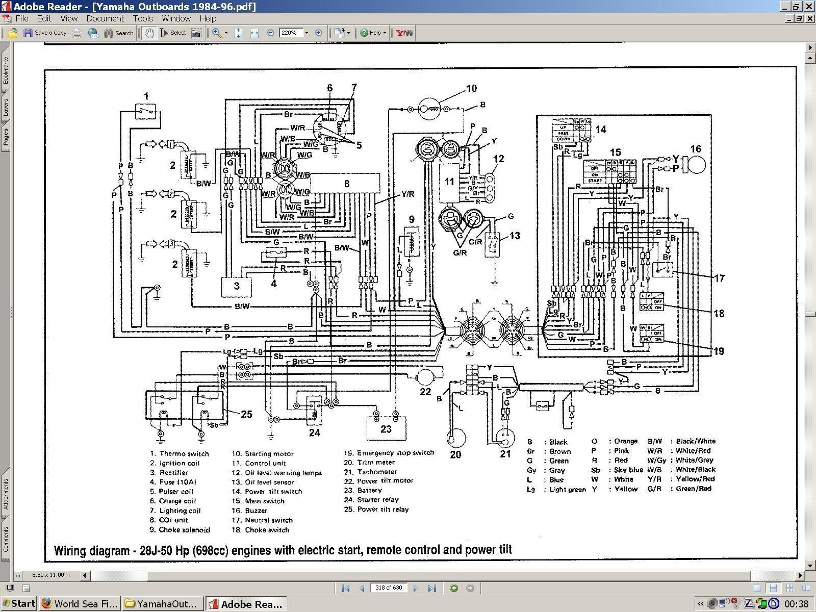
Yamaha 703 Remote Control Wiring Schematic
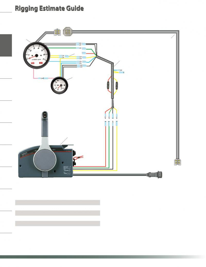
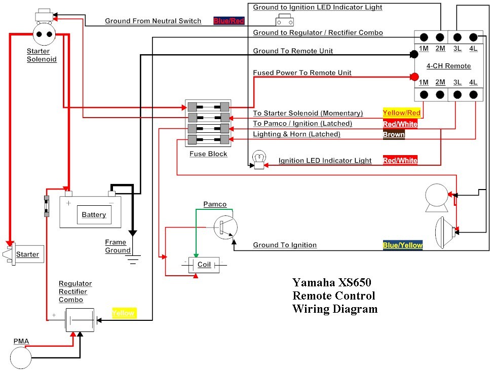
Yellow is ignition supply to guages, green is tach signal, red is constant 12v for digital speedo memory (wont turn on without it), black is ground. Here is standard rigging wiring.
703 Yamaha Remote Control Wiring Diagram Collection
36 volt golf cart wiring diagram wiring diagram.
Yamaha 703 remote control wiring schematic. Whaleflo yamaha outboard 703 premium side mount remote control 48205 16 00 for marine box manufacturer from china 108790654. We will share this […] Yamaha 703 remote control wiring diagram carfindernet com.
Mar 10, · remote control wiring help , am i am having to rewire a remote control to my yamaha etlh 70 hp. With this kind of an illustrative guide, you’ll have the ability to troubleshoot, avoid, and complete your projects easily. Yamaha 703 remote control wiring diagram.
Yamaha control box wiring schematic diagram. Chiral multidentate oxazoline ligands based on. Yamaha remote control wiring diagram usually 4 wires from that box.
Yamaha 703 remote control box wiring diagram. Colors of the wires are red, green, yellow, and black. L30cm 10 pin 703 yamaha outboard remote linkedin wiring diagram manual for control to helm the conrol box ribnet rigging 1994 1996 whaleflo premium genuine need help relocating side.
Click on the image to enlarge, and then save it to your computer by right clicking on the image. I don't know what the yamaha color code might be. Yamaha 50 wiring diagram wiring diagram 500.
I wont need to deal. Collection of yamaha 703 remote control wiring diagram. With this guidebook, you may be able to find out how each.
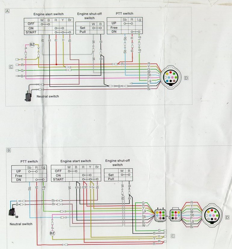
Yamaha 704 remote control service manual. Yamaha 703 wiring diagram online wiring diagram with a 704 yamaha remote control box binnacle mount. The engine provides a ground via the pink wire to cause the buzzer to sound.
Electrical wiring yamaha 703 remote control wiring diagram. It is intended to aid all the common consumer in developing a correct method. L30cm 10 pin 703 yamaha outboard remote control box مصقول.
Wiring diagram for a yamaha remote control box for a outboard motor need to know what. There are 4 individual wires coming out of yamahas 703 control box terminated with bullet connectors. Yamaha remote control wiring diagram usually 4 wires from that box.
There is a buzzer inside the 703 to which the pink wire and the yellow wire are connected. With a 704 yamaha remote control box binnacle mount. Does anyone have a definition for each wire?
Some boxs have no red wire. Some boxs have no red wire. Yamaha 703 remote control wiring diagram.
Colors of the wires are red, green, yellow, and black. 13.05.2019 13.05.2019 0 comments on 703 yamaha remote control wiring diagram there are 4 individual wires coming out of yamaha's control box, you can also find the wiring diagram for the yamaha control box in this. Help needed yamaha tach wiring page 1 iboats boating.
Wiring diagram will come with several easy to stick to wiring diagram guidelines. 21 posts related to electrical wiring yamaha 703 remote control wiring diagram. 688 8258a 10 00 688 8258a 10.
Yamaha 703 remote control wiring diagram usually 4 wires from that box. The original harness was cut and i am installing it on a pontoon with no gauges but engine and control both are set up for power tilt and trim. Control 4 wiring diagramcontrol 4 wiring diagram.
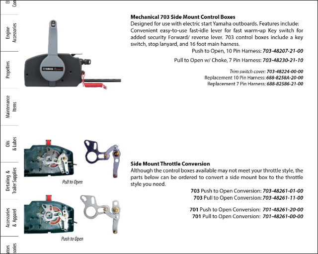
Novelbee side mount remote control box with 10 pins wire harness and cable 16ft for yamaha outboard motors steering system right hand 703 48205 online in vietnam b07z8w7n6x. Us 120 0 marine outboard remote control box yamaha for boat engine with 10 pin push to open on aliexpress. Yamaha 703 remote control box diagram.
There are 4 individual wires coming out of yamaha's control box, terminated with bullet connectors. Yellow provides voltage to the buzzer when the key is on. There are 4 individual wires coming out of yamahas 703 control box terminated with bullet connectors.
I bought the boat used and someone has already been inside the controls cutting on wires so that the boat functions without the kill switch. Damn if i can find out where the pink, black and yellow wires are to go. Kaia.schoen january 26, 2022 templates no comments.
Each component should be set and linked to other parts in particular manner. Yamaha 704 remote control wiring diagram wiring diagram. These guidelines will likely be easy to grasp and implement.
Yamaha 703 control box wiring diagram. Yamaha 703 remote control parts diagram. The wiring color codes are somewhat standard for this, at least with outboard engines manufactured in america.
The original harness was cut and i am installing it on a pontoon with no gaugesbut engine and control both are set up for power tilt and trim. If you are talking wiring inside control box then it only has red,blue and green wire going to trim switch and 2 brown wires going to neutral switch. I believe i have a frozen throttle cable.
Yellow is ignition supply to guages, green is tach signal, red is constant 12v for digital speedo memory (wont turn on without it), black is ground.
Yamaha Outboard Remote Control Wiring Diagram Electrical
Yamaha 703 Control The Hull Truth Boating and Fishing
Pdf5771] Mercury Tohatsu 30Hp 2 Stroke Service Manual
Yamaha Outboard Control Wiring Wiring Diagram Schemas
703 Yamaha Remote Control Wiring Diagram
Wiring Diagram Yamaha 703 Remote Control Automotive
Yamaha 704 Remote Control Wiring Diagram Wiring Diagram

Yamaha Outboard Tachometer Wiring Diagram Cadician's Blog
Yamaha 704 Remote Control Wiring Diagram Wiring Diagram

Yamaha Outboard Electrical Wiring Diagram Yamaha 703

Yamaha Outboard Tachometer Wiring Diagram Wiring Diagram
Yamaha 703 Remote Control Wiring Diagram Wiring Diagram
Tohatsu Outboard Control Wiring Diagram Complete Wiring
Yamaha XS650 Remote Control Wiring Diagram TampaSVT Flickr
Yamaha 703 Remote Control Wiring Diagram Wiring Diagram
Yamaha 703 Remote Control Wiring Diagram
Yamaha Control Box Wiring Diagram Wiring Diagram Schemas
Yamaha F150 Outboard Wiring Diagram PALOTAKENTANG
Yamaha Control Box Wiring Diagram Wiring Diagram Schemas
